

Translate this page into:
Set-up Errors and Determination of Planning Target Volume Margins Protocol for Different Anatomical Sites in a Newly Established Tertiary Radiotherapy Centre in India
Address for correspondence Pritanjali Singh, MBBS, DNB, ESMO, Department of Radiation Oncology, All India Institute of Medical Sciences, Patna 801507, Bihar, India. drpritanjalis@gmail.com
This article was originally published by Thieme Medical and Scientific Publishers Private Ltd. and was migrated to Scientific Scholar after the change of Publisher.
Abstract
Objective Our study aimed to assess the set-up errors for image-guided radiotherapy at a newly established tertiary radiation center in India and to establish the departmental protocol of clinical target volume–planning target volume (CTV–PTV) margins for different anatomical sites.
Materials and Methods This study enrolled the first 200 patients who were treated with curative intent at All India Institute of Medical Sciences, Patna, from February 2019 to September 2019. Number of patients were 53, 26, 53, 11, 6, 47, and 4 for head and neck, brain, breast, thorax, abdomen, pelvis, and craniospinal irradiation (CSI), respectively. The translational vectors for total 1,463 kV cone-beam computed tomography (CBCT) images were collected from the treatment record.
Results For the systematic error, the largest value is found for the thoracic subset on the X and Y directions, and for breast patients on Z axis, whereas the smallest values were found for CSI. For random error, the largest value was found for pelvic in the X, Y direction, and for breast subset on Z axis, whereas the smallest values on X and Z axes were found in the brain and for head and neck on the Y axis. Largest value for systemic error is smaller than 5 mm in all directions and for all anatomical subsets. The highest random error value is 5.07 mm in Y axis for pelvic subset. The largest values for CTV–PTV margin are found for thoracic subset and the smallest for CSI followed by the brain. Significant reduction of set-up error observed for the last hundred patients as compared to the first half of the patient population.
Conclusion Use of thermoplastic cast along with breast board and respiratory motion management should be recommended to reduce set-up error for breast and thoracic subset. Six degrees of freedom robotic couch system can also further rectify the set-up error in image-guided radiotherapy.
Keywords
set-up error
PTV margins
Image-guided radiotherapy

Introduction
Image-guided radiation therapy (IGRT) is intended to deliver the therapeutic radiation after image-based target relocalization ensuring precise delivery of beam and minimizing the volume of organ at risks (OARs) exposed to the ionizing radiation. Determination of the discrepancy between the intended and actual treatment position with the aid of cone-beam computed tomography (CBCT) is an integral part of IGRT.1 This discrepancy is calculated as a shift in treatment field position comparing the CBCT images against its corresponding reference which is known as digitally reconstructed radiographs (DRRs). Set-up error comprises a systematic and random component2 and is calculated over a horizontal axis or right–left (X), longitudinal axis or superior–inferior (Y), and depth or anterior–posterior (Z) axis. It also contains rotational changes which can be corrected if 6 degrees of freedom couch is available in the institute.
The systematic error is a reproducible consistent deviation that occurs in the same direction and magnitude throughout the treatment course. Systematic errors can enter into the treatment chain at any phases of localization, planning or beam delivery. Possible reasons for systematic errors2,3 are (1) target delineation error which represents the difference between the delineated and ideal clinical target volume (CTV); (2) target position and shape error which is due to the tumor regression or growth, bladder and rectum filling difference, hair loss, etc.; and (3) phantom transfer error4 which occurs during image transfer from initial localization through the treatment planning system (TPS) to the linear accelerator (LA). Several factors which might lead to such errors are differences in laser alignment between CT simulator and LA, minor changes in CT simulator couch longitudinal position, image resolution, isocenter location, source to surface distance (SSD) indication, margin growing algorithm, field edge and multileaf collimator (MLC) leaf position, gantry, and collimator angle accuracy. Many of these parameters are expected to be detected by the routine quality assurance program of the machines.5
The random component is a deviation that can vary in direction and magnitude for each delivered treatment fraction. It occurs at the treatment delivery or execution stage and possible reasons6 are (1) patient set-up error which is varying, unpredictable changes due to variation in patient’s daily position, treatment equipment like immobilization devices, or set-up methodology between each delivered fraction; (2) change in target position and shape between fractions due to motion and breathing. These errors are influenced by the immobilization system, patient compliance, and department protocols. Only an off-line correction strategy cannot rectify the random error component in the subsequent fractions. Online correction7 of CBCT is necessary to rectify the random error component.
Set-up errors, CTV–planning target volume (PTV) geometric margins, beam delivery techniques, use of immobilization devices are interlinked. The daily online correction protocol, both for systematic and random error, may increase the treatment time significantly resulting in intrafractional variation. Longer treatment time also necessitates more skilled resources and caregivers which might be limited for high volume radiation centers in India. Volumetric arc therapy (VMAT) which is a single or multiple-arc treatment enables delivery of radiation with much shorter beam on time and lesser monitor units (MU) can reduce the intrafractional set-up errors.8
Our study aims to assess the three-dimensional set-up errors in image-guided fractionated radiotherapy at a newly established tertiary radiation center in India and to establish the departmental protocol of PTV margins for different anatomical sites.
Materials and Methods
Patient Selection
The first two hundred patients who were treated with curative intent in a newly established LA (Elekta Versa HD) at the department of radiation oncology, All India Institute of Medical Sciences, Patna, were enrolled retrospectively since February 2019 to September 2019. The patients were divided as per the following anatomical sites: (1) head and neck (n = 53), (2) brain (n = 26), (3) breast (n = 53), (4) thorax (n = 11), (5) abdomen (n = 6), (6) pelvis (n = 47), and (7) craniospinal irradiation (CSI; n = 4).
Immobilization and Simulation
Before the treatment, all the patients underwent CT scan in head first and supine position. Contrast dye was used as per clinician’s discretion. Patients with squamous cell carcinoma head and neck region (HNSCC) and brain malignancy were immobilized with five clamps and three clamps thermoplastic cast, respectively. Suitable size of head rest (HR) was used for all patients with HNSCC and brain malignancy which were comfortable, reproducible, and fit for the patients. All the women with carcinoma of the breast were simulated with breast board (Micormedics) without a thermoplastic cast. Patients with carcinoma in the thoracic region were comprising with the various diagnosis of malignancy, namely, carcinoma lung, carcinoma oesophagus, soft tissue sarcoma, and lymphoma. Such patients were simulated with proper HR, four clamps thermoplastic casts or Vac-Lok cushion (Civco Medical Solutions trade mark, Iowa, United States). Patients with abdominal malignancy subset who had diagnosis of carcinoma stomach and carcinoma gall bladder were simulated with four clamps thermoplastic cast and HR.9 We followed the “bladder protocol”10 for the patients of the pelvic subsite, with the diagnosis of carcinoma in various pelvic organs namely cervix, endometrium, rectum, anal canal, and prostate. Such patients were asked to void their urinary bladder first and then to consume 500 mL of water 30 minutes before the simulation and to hold the urine till the simulation is complete. Knee rest was used for immobilization as per clinician’s discretion. Children with the diagnosis of medulloblastoma, who were treated with CSI were immobilized with HR, three clamp thermoplastic cast for brain region, and Vac-Lok for the torso.
Fiducial Markers
The external markers for patients with brain tumor and HNSCC were placed on the surface of the fixation masks with the aid of CT simulation in-room laser in three directions (right, left, and roof).11 Patients with breast carcinoma were marked with skin tattoos in three positions (preferably on right and left midaxillary line and midline of the body) with the alignment of the room laser. Patients immobilized with Vac-Lok had three markers, one on the patient body and another two on the Vac-Lok. For patients treated with CSI, Three fiducial markers were kept for brain region and another three fiducial markers on Vac-Lok
Image Acquisition and Registration of Planning CT to CBCT
The CT simulation of all patients is undergone with GE Healthcare Optima full-rotation helical 16-slice CT scanner. Brain images are taken with 3-mm slice thickness while the rest of the sites underwent 5-mm slice images. These CT images were transferred to the Monaco 5.0 TPS. If available, magnetic resonance imaging (MRI), and positron emission tomography scan (PET) for any subsites were registered with CT simulation images for the better delineation of gross tumor volume (GTV).
For the first day treatment set-up, the patients were positioned according to the fiducial marker by using in-room set-up laser. Thereafter, kV-CBCT images were acquired using the gantry-mounted X-ray volume imaging (XVI).
The registration between the acquired CBCT images and planning CT images (DRR) was performed by bone and/or soft tissue grey value automatching followed by a manual correction if required. Rigid bony anatomy (vertebral column), visualized target volume within the PTV, adjacent landmarks, such as the carina or bronchus, bladder, and rectum filling difference, were taken into account during the process of manual matching. The translational position correction vectors were calculated after the whole matching procedure for lateral, longitudinal, and vertical axis.12
The clinical threshold level at our institution is 5 mm and 3 degrees for both translational and rotational directions. In cases of larger deviations, the patient was repositioned and online registration was performed again.
Methods of Data Analysis
The translational vectors for total 1,463 kV CBCTs images were collected from the treatment record. Individual average of shifts along the three-axis and standard deviation (SD) were calculated for each patient. Total average of the SD, minimum, and maximum value for each treatment sites were analyzed. Set-up errors are normally distributed and mean (M) and SD of errors most accurately describe them. M is defined as the mean of all individual means and ideally, it should be closer to zero. S corresponds to the SD of all individual means, and σ is determined through the root mean square of the individual SD of all patients.
According to the literature of The Royal College of Radiologist, Institute of Physics and Engineering in Medicine and Society and College of Radiographers are on target, ensuring geometric accuracy in radiotherapy.3 The errors are categorized as follows.
Systematic Error
Individual Mean Set-up Error
Individual mean set-up error (mind) is the mean set-up error for an individual patient:
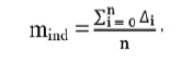
where ∆i is the set-up error for each imaged fraction and n is the number of imaged fractions.
Overall Population Mean Set-up Error
The overall mean set-up error (Mpop) is the overall mean for the analyzed patient group and should ideally be zero. Significant deviation from zero indicates an underlying error common to the patient group and requires corrective measurements. The equation to calculate the overall population mean set-up error is as follows:
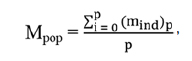
where mind is the individual mean set-up error and p is the number of patients.
Population Systematic Error
The systematic error for the population (∑set-up) is defined as the SD of the individual mean set-up errors about the overall population mean (Mpop). It is calculated from the following equation:
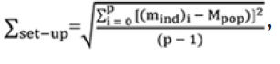
where mind and Mpop are individual and overall population systematic set-up error respectively and p is the number of patients.
Random Error
Individual Random Error
For each individual, the interfractional random (daily) set-up error (σind) is the SD of set-up errors around the corresponding mean individual value (mind) derived from equation (01).
It is calculated from the following formula:
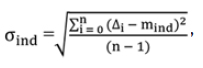
where σind and mind are the individual random error and individual mean set-up error. ∆i is the set-up error for each imaged fraction and n is the number of imaged fraction.
Population Random Error
The population random error (σset-up) is the mean of all the individual random errors.
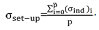
where σind is the individual random error, calculated from equation (04) and p is the number of patients.
Calculation of PTV Margin
There are several methods to calculate CTV to PTV margin like the International Commission on Radiation 62 (PTV margin = ∑+0.7σ), Stroom’s method (PTV margin = 2 ∑+0.7σ), and Van Herk’s (PTV margin = 2.5 ∑+0.7σ) formula. Here ∑ and σ are the population systematic error and population random error, respectively. For our institutional practices, the general margin is calculated form Van Herk’s equation. Analysis is carried out using the Microsoft Office Excel 2013 and graphs are made with OriginLab (OriginLab Corporation, Northampton, Massachusetts, United States)
Results
The average shifts for all the patients in our study including all the treatment sites in three directions are shown in Fig. 1, and the values of M, systematic error, and random error for each anatomical subset are shown in Table 1.
|
Site |
No. of patients |
No. of kv-CBCT |
Mean (mm) |
Systematic error (∑) in mm |
Random error (σ) in mm |
||||||
|---|---|---|---|---|---|---|---|---|---|---|---|
|
X |
Y |
Z |
X |
Y |
Z |
X |
Y |
Z |
|||
|
Brain |
26 |
202 |
0.264 |
0.476 |
0.419 |
1.106 |
1.347 |
1.001 |
1.658 |
2.020 |
1.328 |
|
Head and neck |
53 |
436 |
0.203 |
0.253 |
0.035 |
1.091 |
0.767 |
1.924 |
2.205 |
1.490 |
1.928 |
|
Thorax |
11 |
83 |
0.055 |
0.319 |
0.348 |
3.347 |
3.670 |
1.346 |
2.425 |
3.053 |
2.350 |
|
Breast |
53 |
309 |
0.198 |
0.211 |
1.441 |
2.771 |
3.344 |
2.986 |
4.423 |
3.903 |
3.879 |
|
Abdomen |
6 |
46 |
0.068 |
2.592 |
0.116 |
1.274 |
2.254 |
1.799 |
1.997 |
2.721 |
2.818 |
|
Pelvic |
47 |
347 |
0.031 |
0.064 |
0.684 |
2.753 |
2.323 |
1.419 |
4.554 |
5.077 |
3.130 |
|
CSI |
4 |
40 |
0.025 |
1.730 |
0.200 |
0.588 |
0.751 |
0.651 |
2.291 |
2.263 |
1.374 |
Abbreviation: CBCT, cone-beam computed tomography; CSI, craniospinal irradiation.
-
Fig. 1 Average shifts for all the patients in our study including all the treatment sites in three directions. Avg., average.
For the systematic error, the largest value is found for the thoracic subset on the X and Y directions, and breast patients on Z axis, whereas the smallest values were found for CSI. Apart from CSI, lowest values are found on X and Y axes for head and neck subset and on Z axis, lowest value is for the brain. For random error, the largest value was found for pelvic in the X, Y direction, and for breast on Z axis, whereas the smallest values on X and Z axes were found in the brain and for head and neck on the Y axis.
In overall, the largest value for systematic error is smaller than 5 mm in all directions and for all anatomical subsets. For random error, the highest calculated value is 5.07 mm in Y axis for pelvic subset.
For the better evaluation of our continuous effort to reduce the set-up errors, we analyzed the systematic and random errors for first hundreds and second hundreds of patients irrespective of the anatomical sites. The results are calculated in Tables 23.
|
No. |
Systematic error (∑) (mm) |
Random error (σ) (mm) |
||||
|---|---|---|---|---|---|---|
|
X |
Y |
Z |
X |
Y |
Z |
|
|
1st 100 patients |
2.506 |
2.507 |
2.169 |
3.300 |
3.152 |
2.520 |
|
2nd 100 patients |
1.910 |
2.040 |
1.403 |
3.263 |
2.992 |
2.565 |
|
No. |
Technique |
Systematic error (∑) in mm |
Random error (σ) in mm |
||||
|---|---|---|---|---|---|---|---|
|
X |
Y |
Z |
X |
Y |
Z |
||
|
1st 100 patients |
3DCRT |
3.141 |
2.891 |
1.991 |
4.057 |
3.979 |
2.744 |
|
2nd 100 patients |
1.225 |
1.903 |
2.254 |
2.336 |
2.099 |
2.234 |
|
|
1st 100 patients |
VMAT/IMRT |
2.067 |
2.475 |
1.721 |
4.077 |
3.713 |
3.273 |
|
2nd 100 patients |
1.743 |
1.432 |
0.928 |
2.480 |
2.299 |
1.885 |
|
Abbreviations: 3DCRT, three-dimensional conformal radiation therapy; IMRT, intensity-modulated radiation therapy; VMAT, volumetric arc therapy.
CTV-to-PTV Margin
For each treatment site, the calculated CTV-to-PTV expansion values for the overall sessions are presented in the Table 4. The largest values are found for thoracic subset and the smallest for CSI followed by the brain. These results are in expected range because of the values of systematic and random errors computed in our study.
|
Site |
No. of patients |
X (lateral) in mm |
Y (longitudinal) in mm |
Z (vertical) in mm |
Margin (mm) |
|---|---|---|---|---|---|
|
2.5*∑+0.7*σ |
2.5*∑+0.7*σ |
2.5*∑+0.7*σ |
|||
|
Brain |
26 |
3.9 |
4.8 |
3.4 |
4.8 |
|
Head and neck |
53 |
4.3 |
3.0 |
6.2 |
6.2 |
|
Thorax |
11 |
10.1 |
11.3 |
5.0 |
11.3 |
|
Breast |
53 |
10.0 |
11.1 |
10.2 |
11.1 |
|
Abdomen |
6 |
4.6 |
7.5 |
6.5 |
7.5 |
|
Pelvic |
47 |
10.1 |
9.4 |
5.7 |
10.1 |
|
CSI |
4 |
3.1 |
3.5 |
2.6 |
3.5 |
Abbreviations: CSI, craniospinal irradiation; CTV, clinical target volume; PTV, planning target volume.
Discussion
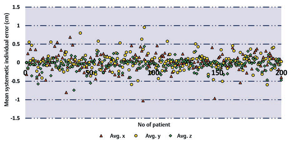
Interfraction set-up errors for seven different treatment sites of the first two hundred treated patients at our institute were analyzed retrospectively using 1,463 CBCT studies. The mean error and the SD on three axes are shown in the Figs. 234.
-
Fig. 2 Mean errors and the standard deviation for lateral axis for different treatment sites.
-
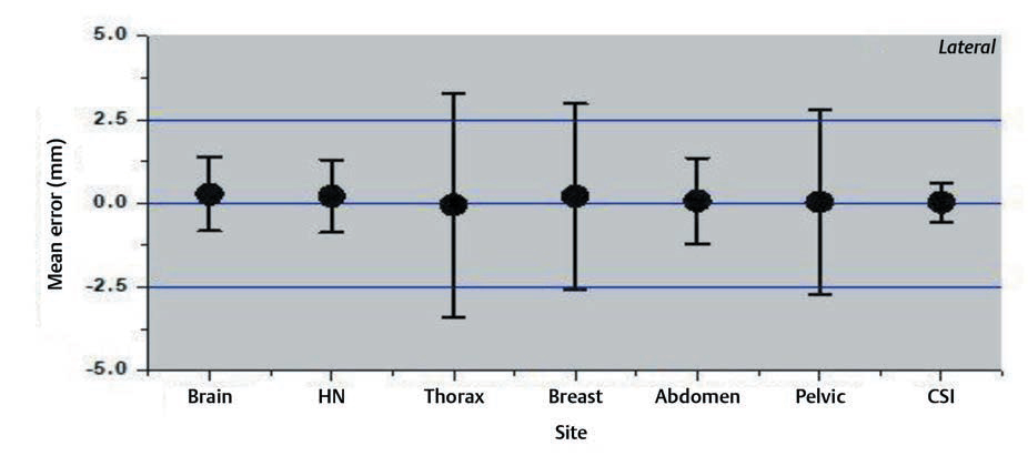
Fig. 3 Mean errors and the standard deviation for longitudinal axis for different treatment sites.
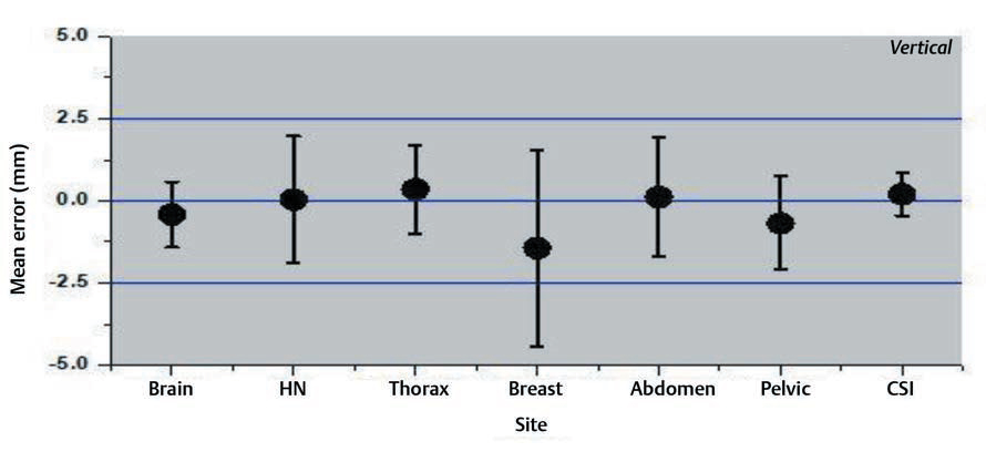
-
Fig. 4 Mean errors and the standard deviation for vertical axis for different treatment sites.
For intrafraction variation, several studies13 showed that intrafraction tumor deviation is significantly greater if the interval between target localization and repeat CBCT imaging is more than 34 minutes. The average time from localization to treatment in our institution is approximately 15 minutes.
The results of our study showed that the variation was large for breast and thoracic subset and small for CSI and brain treatments. The large values for the thoracic region are probably due to the free breathing motion. The use of only breast board without immobilization cast and improper localization of skin tattoos might have resulted in a larger shift for breast cancer subset. Several factors like curved external anatomy, loosening, or tightening of the fixation mask due to changing body contours, tumor shrinkage can also contribute to significant set-up errors. Keeping such changes in mind, rescanning and replanning with new fixation mask were done in our institution if considerable discrepancies occurred.14,15,16
Multiple studies17,18 have recommended the reduction of PTV margins with the use of CBCT image guidance. PTV margin without image-guided radiation therapy should be ≥5 mm, whereas, with daily CBCT image guidance, it could be reduced to approximately 2 to 3 mm. The calculated PTV margins of approximately 3.5 to 4.8 mm in all translational directions for the brain and CSI treatment sites in our institution were in tune to available published studies. Therefore, reduced PTV margins for the brain and CSI should be applied under daily CBCT imaging guidance. For thoracic and pelvic subsites, the PTV margins were mainly affected by set-up errors due to respiratory motion, tumor shrinkage, nonuniform protocol for the use of thermoplastic casts.
With our analysis of the second half of the patient population, we found a significant improvement in terms of set-up errors for both systematic and random component which was consistent with three-dimensional conformal radiation therapy, intensity-modulated radiation therapy, and VMAT techniques. Gaining more expertise and efficiency by the radiation technologists for patient simulation, molding of thermoplastic casts, patient positioning, and localization in treatment couch and more uniform use of thermoplastic devices and skin markings with ink tattoos can explain this significant improvement.
Limitations
One of the limitations which need to be addressed for this study is the unavailability of 6 degrees of freedom robotic couch system in our institute and hence not accounting the rotational changes in the analysis. Not taking a second or verification CBCT scan after the repositioning and not accounting the residual errors after matching is another drawback of our CBCT protocol. Second CBCT will also lead to a higher dose of exposure to the patient and longer treatment time. But the assessment of the residual errors might help to calculate CTV-to-PTV expansion margins more accurately when IGRT is followed.
Conclusion
Based on the result and observations of this study, we recommend the following four points to be addressed for our future treatment:
-
To use thermoplastic immobilization masks along with breast board for all patients with carcinoma breast.
-
The patients who follow bladder protocol are to consume uniform volume of water with a uniform time gap between water intake and simulation and water intake and treatment.
-
Six degrees of freedom robotic couch system for correction of rotational errors is to be installed.
-
Respiratory motion management devices should be considered especially for breast carcinoma and thoracic malignancy subsets.
Acknowledgement
The authors would like to thank the staff of Department of Radiotherapy, AIIMS Patna.
Conflict of Interest
None declared.
References
- Image guided radiotherapy (IGRT) via online cone beam CT substantially reduces margin requirements for stereotactic lung radiotherapy. Int J Radiat Oncol. 2007;69(03):S154.
- [Google Scholar]
- On target: ensuring geometric accuracy in radiotherapy. https://www.rcr.ac.uk/system/files/publication/field_publication_files/BFCO%2808%295_On_target.pdf. Accessed January 24, 2020
- A systematic evaluation of the error detection abilities of a new diode transmission detector. J Appl Clin Med Phys. 2019;20(09):122-132.
- [Google Scholar]
- Investigation of error detection capabilities of phantom, EPID and MLC log file based IMRT QA methods. J Appl Clin Med Phys. 2017;18(04):172-179.
- [Google Scholar]
- Assessment of three-dimensional set-up errors in conventional head and neck radiotherapy using electronic portal imaging device. Radiat Oncol. 2007;2(01):44.
- [Google Scholar]
- Image guidance in radiation therapy: techniques and applications. Radiol Res Pract. 2014;2014:705604.
- [Google Scholar]
- Evaluation of volumetric modulated arc therapy (VMAT) with Oncentra MasterPlan for the treatment of head and neck cancer. Radiat Oncol. 2010;5(01):110.
- [Google Scholar]
- Development of patient support devices for execution of clinical radiotherapy for cancer patients: A preliminary report. J Med Phys. 2006;31(04):255-261.
- [Google Scholar]
- EP-1616: A review of bladder filling protocols for patients receiving radical pelvic radiotherapy. Radiother Oncol. 2015;115:S885-S886.
- [Google Scholar]
- Evaluation of different fiducial markers for image-guided radiotherapy and particle therapy. J Radiat Res (Tokyo). 2013;54(01):i61-i68.
- [Google Scholar]
- Applications of linac-mounted kilovoltage cone-beam computed tomography in modern radiation therapy: a review. Pol J Radiol. 2014;79:181-193.
- [Google Scholar]
- Quantifying interfraction and intrafraction tumor motion in lung stereotactic body radiotherapy using respiration-correlated cone beam computed tomography. Int J Radiat Oncol Biol Phys. 2009;75(03):688-695.
- [Google Scholar]
- Adaptive radiotherapy for head and neck cancer. Technol Cancer Res Treat. 2017;16(02):218-223.
- [Google Scholar]
- The use of adaptive intensity-modulated radiotherapy in the treatment of small-cell carcinoma lung refractory to chemotherapy in a patient with preexisting interstitial lung disease. Lung India. 2018;35(01):54-57.
- [Google Scholar]
- Samuels M.2018 Update on Radiation Treatment for Head/Neck Cancer. Available at: https://www.astro.org/uploadedFiles/_MAIN_SITE/Meetings_and_Education/ASTRO_Meetings/2018/Annual_Refresher/Content_Pieces/2018RefresherHeadNeck.pdf. Accessed March 31, 2020
- Quantification and assessment of interfraction setup errors based on cone beam CT and determination of safety margins for radiotherapy. 11:e0150326. PLoS One
- [Google Scholar]
- Estimation of setup uncertainty using planar and MVCT imaging for gynecologic malignancies. Int J Radiat Oncol Biol Phys. 2008;71(05):1511-1517.
- [Google Scholar]


